تطورت خطة المعالجة بالزرعات السنية خلال السنوات الماضية لتشمل في بعض الحالات التثبيت في القوس العذارية بدلا من التثبيت في الفك العلوي .
يجري هذا النوع من الجراحة في حالات وجود امتصاص شديد متفاقم في الفك العلوي و عندما لا يكون هناك إمكانية لوضع الزرعات التقليدية .
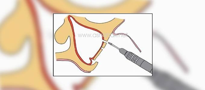
تدخل الزرعات من الجهة الحنكية في عظم الفك العلوي (منطقة الضواحك)إلى المنطفة العظمية الجيدة والتي تتوضع في الزاوية العلوية الوحشية من العظم الوحني .
تدخل الزرعات بشكل مستقيم عبر الجيب الفكي , ونظراً للتعقيد التشريحي لهذا المثلث الصغير و المترافق برؤية محدودة لذلك يعد التحضير و التخطيط الدقيق قبل العمل الجراحي أساسياً للحصول على نتيجة جراحية جيدة .
أعدت لعدد من الحالات خطط عبر نظام تخطيط خاص بهذا النوع من الجراحة حيث يمر مسار الحفر عبر المحور الطولي للزرعة و هو أمر أساسي للعبوور خلال البنى التشريحية لهذه المنطقة .
للحصول بشكل عام على خطة كاملة للمعالجة توضع زرعتين للقوس العذارية في الجهتين ثم تشارك بزرعتين طويلتين أكثر ما يمكن في المنطقة الأمامية حيث يمكن الحصول على ذلك عبر هذا المخطط و من خلال فحص شعاعي مقطعي ثلاثي الأبعاد يمكن معرفة أقصى عمق ممكن أن يصل إليه الجراح .(الشكل)
كما يعطي فكرة دالة و إرشادية للعمل حيث تلاحظ دوماً مع هذه الإجراءات تعقيدات محيطة بالمنطقة (بسبب المجاورات التشريحية المتعددة و المعقدة و الخطرة ) . تبين في الصورة الثانية منظر عبر محور الزرعة و ما يحيط به .
تعليق إضافي :
طول هذه الزرعات 52 – 75 ملم يترافق العمل بها بمجموعة أدوات و سنابل حفر خاصة و ممددات و مبعدات خاصة للحماية و لعل أهم منطقة يؤكد على حمايتها بمساعد جرّاح خاص لها هو المنطقة تحت جوف الحجاج الأيسر .
الشكل : تشاهد زرعتين عذاريتين طويلتين مشار إليهما بحرف Z و زرعتين أماميتين مشار إليهما بحرف F أما الشكل الأيمن فهو مقطع على طول محور الزرعة حيث تشاهد بمجاوره الحفر الأنفيةN الجيب الفكي Sو الذي اخترقته الزرعة لتصل إلى العظم الوجني
Extending an oral implant planning system towards zygoma implants
Our planning system for oral implants surgery, developed during previous years is adapted for implants to be placed in the Os Zygomaticum instead of in the maxilla. This type of surgery is done in cases of extreme bone resorption, where it is impossible to place ordinary alveolar implants. The implants are inserted in the palatal side of the maxillar ridge and are aimed at the bone of very good quality that can be found at the upper outer angle of the zygoma. The trajectory goes straight through the sinus. Due to the complicated anatomy and the small size of the target zone, combined with a limited visibility, a meticulous preoperative planning is essential for a good surgical result. Several cases were planned with the planning system, and the system was tuned for this specific type of surgery. It turned out that a reslicing along the axis of the implants was essential for a good insight into the anatomy of this region. Moreover, the ability to obtain an oversight of the configuration as a whole (2 zygoma screws and two longer frontal implants) and the combination of the 3D surface rendered models provided the extra depth which facilitated orientation (see Figure). Since there is always an orientation problem in such a complex surrounding, the second window showing a view along the axes or perpendicular to them was invaluable.
Our planning system for oral implants surgery, developed during previous years is adapted for implants to be placed in the Os Zygomaticum instead of in the maxilla. This type of surgery is done in cases of extreme bone resorption, where it is impossible to place ordinary alveolar implants. The implants are inserted in the palatal side of the maxillar ridge and are aimed at the bone of very good quality that can be found at the upper outer angle of the zygoma. The trajectory goes straight through the sinus. Due to the complicated anatomy and the small size of the target zone, combined with a limited visibility, a meticulous preoperative planning is essential for a good surgical result.
Several cases were planned with the planning system, and the system was tuned for this specific type of surgery. It turned out that a reslicing along the axis of the implants was essential for a good insight into the anatomy of this region. Moreover, the ability to obtain an oversight of the configuration as a whole (2 zygoma screws and two longer frontal implants) and the combination of the 3D surface rendered models provided the extra depth which facilitated orientation (see Figure). Since there is always an orientation problem in such a complex surrounding, the second window showing a view along the axes or perpendicular to them was invaluable
Figure – Two long zygoma screws are seen at Z, and two frontal screws at F. The right image is a section along the screw axis. Note the nearby nasal cavity (N) and the sinus (S), which is penetrated by the screw.
P. Suetens, G. Marchal, J. Van Cleynenbreugel, F. Schutyser (in collaboration with D. van Steenberghe, Division of Periodontology, K.U.Leuven and C. Malevez, Department of Maxillofacial Surgery, Hôpital Erasme, Université Libre de Bruxelles)
ترجمة الدكتورفيصل السبيعي
 أسنانك . نت أكبر مرجع عربي لطب الأسنان على الانترنيت


